アンテナ近傍界計測システム
Software features
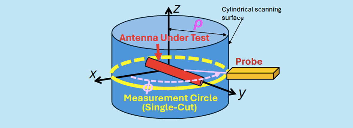
This is the one of single-cut near-field to far-field and near-field transformations. We call this as Kim method because the fundamental equation has been derived Dr. Jeong-Hwan Kim and Dr. Hong-Ki Choi in KRISS in the 2005 paper. Using the equation of Kim method, the absolute gain patterns for low-height antennas in the XY plane can be obtained through the probe compensation. In addition, our software can calculate
near-field electric-field pattern in the XY plane at any distance from the antenna center (near-field to near-field transformation).
Only the measured s21 on a circle is used as the input data or Only the near-electric fields (φor θcomponents) are used.
Probe coefficients are obtained by the far-field patterns calculated by simulators.
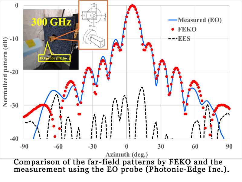
In the following, the software operation is explained using the measured data of the standard horn antenna at 300 GHz.
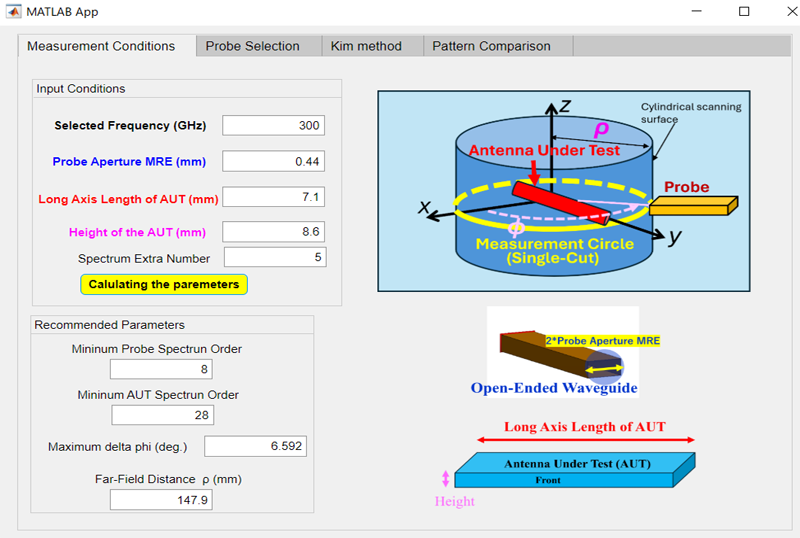
Fist let’s determine the measurement conditions using the Measurement Conditions TAB.
The frequency and the antennas under test (AUT) are selected before the measurement. Let’s set the MRE of the probe used and the long axis length L and the height H of the AUT in each column. The spectrum extra number (default is 5) is the number added to the normal spectrum number such as kL/2. Pushing the Calculating the parameters Botton gives the minimum spectrum orders of the probe and the minimum distance determined by 2*H/λ. In the following steps, those parameters are used.
Probe coefficients are calculated using the Probe Selection TAB.
The probe coefficients are calculated here. The input items are the directory name, the file names for the amplitude (linear) and phase (degrees) of the far-field patterns. Each file includes [phi(deg), value(theta component) , value(phi component)] where the value linear amplitude or phase(degrees).
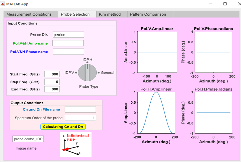
In the probe type switch, select IDP if using the ideal (infinitesimal) electric dipole or General if using the probe with the far-field patterns.
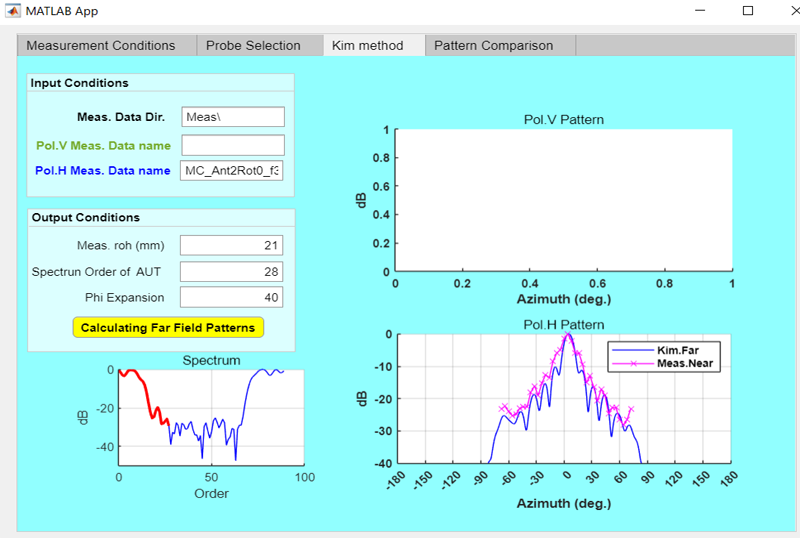
Far-field calculation by Kim method in the Kim method TAB.
In this tab, the absolute far-field patterns are calculated by Kim method.
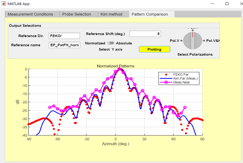
Comparison of the calculated patterns with the reference patterns in the Pattern Comparison TAB.
In this tab, the calculated results by Kim method and the reference patterns are compared in the same figure.